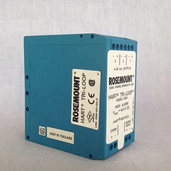
- Almost all HART host systems today are designed to communicate in poll / response mode, not burst mode. Some non-traditional hosts such as the Rosemount 333 Tri-Loop use burst mode to convert multi-variable information to 4-20mA analog signals. A wired HART Revision 5 or 6 device can be configured to burst all process variables.
- Tri-Loop wiring. Configure Tri-Loop Channel 1: a. Assign variable: Tri-Loop HART command 1,2,2,1,1. Make sure that the SV, TV, and QV match the configuration of the 5300 transmitter. Assign units: Tri-Loop HART command 1,2,2,1,2. Make sure that the same units are used as for the 5300 transmitter. Page 119: Hart Multi-Drop.
- HART Tri-Loop Configuration The HART Tri-Loop Configurator can be fully configured using the. Configuration hardware and software may be ordered separately. 33 HART® Tri- Loop™ Signal Converter. The Rosemount 3. 33 HART Tri- Loop enables the conversion of a digital multivariable HART signal into three independent 4- 2. 01: HART Configurator.
For selected devices, we offer software for flexible configuration/calibration and GSD/DD files for bus communication
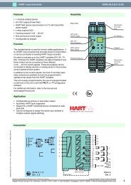
HART Loop Converter 1-channel isolated barrier, 24 V DC supply (Power Rail), HART field device input with transmitter power supply, Usable as signal splitter (1 input and several outputs), 2 relay contact outputs (change-over contacts), 3 analog outputs 4 mA. 20 mA, Sink and source mode output, Configurable by keypad pa.
PReset software for PC
For users who prefer PCs, certain devices are PC-programmable and can be easily and flexibly configured with our PReset software. With this Windows-based program, it’s possible to configure, calibrate, and detect device sensor errors from the comfort of your PC.
Read more and download PReset.


Files for HART and bus communication
Devices with integrated bus communication need GSD/DD files in order to function. A GSD/DD file contains the information that allows the transmitter to communicate with the bus system.
Read more and download.
If you need support with devices or documentation, you are always welcome to contact us.

If you need support with devices or documentation, you are always welcome to contact us.

Hart Tri Loop Configuration Software Interface
Datasheet excerpt: Technical data of HM-MT-USB-010031
| Product Description | ||
|---|---|---|
| Interface for commissioning, calibrating, and acquiring data from HART field devices | ||
Hart Tri Loop Configuration Software Pdf
| Supply | ||
|---|---|---|
| Input current | 30 mA at 5 V | |
| Power supply | Powered by USB port , No external power required | |
| Interface | ||
| Interface type | USB port | |
| Output | ||
| Signal | 0.5 ± 0.1 Vpp trapezoidal wave at 1200/2200 Hz, 24 VDC at 40 mA to device | |
| Galvanic isolation | ||
| Output/interface | 1500 V DC | |
| Directive conformity | ||
| Electromagnetic compatibility | ||
| Directive 2014/30/EU | EN 61326-1:2013 | |
| RoHS | ||
| Directive 2011/65/EU (RoHS) | EN 50581:2012 | |
| System requirements | ||
| Operating system | Windows® 98 , 2000 , 32-bit XP , 32-bit Vista , 32- and 64-bit Windows® 7, and Windows® 10 | |
| Ambient conditions | ||
| Operating temperature | -20 ... 50 °C (-4 ... 122 °F) | |
| Storage temperature | -20 ... 60 °C (-4 ... 140 °F) | |
| Relative humidity | 0 ... 95 % non-condensing | |
| Mechanical specifications | ||
| Degree of protection | IP20 | |
| Connection | USB (type A) Connector , red and black test clips | |
| Material | Polycarbonate | |
| Dimensions | 75 mm x 33 mm x 15 mm | |
| Cable length | 1.8 m 2-strand wire terminating in 2 test clips , 15.2 cm cable terminating in 1 USB type A connector | |
| General information | ||
| Supplementary information | Observe the certificates, declarations of conformity, instruction manuals, and manuals where applicable. For information see www.pepperl-fuchs.com. | |